What the API 5L X52 Manufacturing Process Must Deliver
API 5L X52, written L360 in the ISO 3183 and GB/T 9711 numbering systems, is a medium-strength line pipe steel with a specified minimum yield strength of 359 MPa (52 ksi) and a specified minimum tensile strength of 455 MPa. Buying X52 is not the same as buying a general structural tube. The purchase carries three mandatory performance obligations at once: pipe body and weld seam must both reach the grade strength, every joint must pass a mill hydrostatic test without leakage, and for the PSL 2 product level the heat analysis must stay below the carbon and carbon-equivalent ceilings that allow field girth welding without preheat in most climates. Meeting those obligations is the job of the manufacturing process, which is a chain of controlled steps rather than a single mill operation.
The process is usually described in five blocks - raw material, forming, heat treatment, inspection and coating - but a mill that only controls five blocks will ship pipe with scattered dimensional or toughness failures. The practical breakdown is nine steps with a defined hold point at each: raw material verification, cutting and edge preparation, forming, seam welding or hot piercing, seam heat treatment, sizing and straightening, end finishing and beveling, testing and nondestructive examination, and finally coating, marking and bundling. The paragraphs below follow that chain in production order and state, for each step, which parameter a purchaser has to see verified on the inspection documents.
Step 1: Raw Material Verification Before Any Metal Is Cut
Strength in an X52 pipe is largely decided before the steel reaches the pipe mill. Coil, plate or round billet is ordered to a chemistry window that satisfies both the final mechanical property requirement and the weldability ceiling. For PSL 2 X52 the carbon maximum is 0.22 % for welded pipe and 0.24 % for seamless pipe, manganese is capped at 1.40 %, phosphorus at 0.025 % and sulphur at 0.015 %, with the carbon equivalent limited to 0.43 on the CE(IIW) basis or 0.25 on the Pcm basis, where the Pcm figure applies when carbon is 0.12 % or below. Those ceilings are the reason a mill cannot simply buy cheap high-carbon strip and "fix" the strength in the furnace.
Three documentary checks belong to this step. First, the heat number on the incoming coil or billet tag must match the mill certificate, and the certificate must show ladle analysis values inside the ordered window with product analysis retained in the file. Second, the incoming material must be identified by grade so that an L245 or L290 heat cannot migrate into an X52 order; colour coding plus physical tagging is the normal control. Third, the mechanical properties of the coil - yield strength, tensile strength and Charpy absorbed energy at the ordered test temperature - must be confirmed, because a coil that is already at 420 MPa yield has less room to move during forming and welding. Purchasers should request that the coil certificate heat number is transcribed onto the pipe marking, which closes the traceability loop from slab to coated joint.
Step 2: Slitting, Edge Preparation and Forming Route Selection
Coil is slit to the developed width that corresponds to the ordered outside diameter and wall thickness, then the edges are milled or scarfed to a clean square face before welding. Edge condition is a quality variable that is easy to overlook: a burr or a rolled-over edge creates lack-of-fusion defects that ultrasonic testing will later reject, and the rework cost falls on whoever owns the pipe at that point. Width tolerance and camber matter equally, because a 1 mm width error translates directly into a diameter error after forming.
The forming route is selected by diameter, wall thickness and volume. Small and medium diameters up to roughly 610 mm are formed from coil on continuous roll-forming stands and welded by high-frequency electric resistance or induction welding. Large-diameter line pipe is formed either on a U-O-E press train, where the plate is first pressed into a U, then into an O, then welded and finally mechanically expanded, or on a three-roll bending machine for J-C-O configurations. Spiral submerged arc welded pipe is formed from coil on a helical line, which lets one coil width serve many finished diameters and is why spiral pipe is common in the 610 mm to 1 500 mm range.
| Route | Start material | Typical finished size range | Strength route | Governing reference |
|---|---|---|---|---|
| Seamless, hot pierced | Round billet | 60.3 mm to 660 mm OD | Chemistry plus normalizing or as-rolled microalloying | API 5L, ISO 3183 |
| HFW / ERW | Hot rolled coil | 21.3 mm to 610 mm OD | Chemistry plus weld seam normalizing | API 5L, ISO 3183 |
| SAWL, U-O-E with expansion | Plate | 406 mm to 1 500 mm OD | TMCP plate or normalizing | API 5L, ISO 3183 |
| SAWH, spiral | Hot rolled coil | 219 mm to 3 000 mm OD | TMCP or normalized coil | API 5L, ISO 3183 |
Step 3: Seamless Piercing and Its Temperature Window
On the seamless route the billet is heated to roughly 1 200 °C to 1 280 °C in a rotary hearth or walking beam furnace and soaked until the core reaches temperature, then pierced on a cone-type or cross-roll piercer to create a thick-walled hollow. The hollow is elongated on a plug mill, mandrel mill or three-roll mill, then sized and straightened. Temperature uniformity along the billet length is the single most important variable at this stage: a cold nose produces eccentric wall and a hot tail produces surface laps. Modern mills monitor billet temperature at the furnace exit and reject billets outside the window rather than trying to correct downstream.
X52 on the seamless route is normally supplied in the as-rolled or normalized condition, because the grade sits low enough in the strength spectrum that microalloying with niobium, vanadium and titanium plus controlled finish rolling reaches 359 MPa without a quench and temper operation. Where a customer specifies impact testing at low temperature, the mill will normally add normalizing at 880 °C to 940 °C followed by air cooling, which refines grain size and buys toughness at a small cost in yield strength. That trade-off is worth understanding: normalizing an already lean X52 chemistry can pull yield strength toward the lower limit, so the mill compensates in chemistry rather than in the furnace.
Step 4: Welding on the Welded Routes
High-frequency welded pipe uses induction or contact coils to bring the abutting edges to welding temperature by resistance heating, then squeezes them together between pressure rolls. The weld is a solid-state forge weld with no filler metal, so its quality depends on edge alignment, squeeze force, frequency and speed all being held in balance. After welding, the seam passes an induction normalizing coil that re-heats the weld zone to about 900 °C to 950 °C and air cools it, which removes the hard, coarse structure created by the thermal cycle and restores toughness. On X52 the seam heat treatment is essentially mandatory for PSL 2 pipe intended for low-temperature Charpy testing.
Submerged arc welded pipe runs the seam in two passes, one inside and one outside, using multiple wire electrodes under a granular flux blanket. Heat input is the controlling variable: too high a heat input coarsens the heat-affected zone and lowers Charpy energy, while too low a heat input raises hardness and hydrogen cracking risk on thick walls. Mills therefore qualify a welding procedure with a heat input window per wall thickness and hold the recorded current, voltage and travel speed against that window for every joint. For X52 the weld metal is normally slightly overmatched to the 455 MPa tensile minimum, and the procedure qualification must demonstrate that both weld metal and heat-affected zone reach the required Charpy energy at the specified temperature.
Step 5: Heat Treatment and Thermomechanical Processing Choices
Three delivery conditions are used for X52, and they are not interchangeable in a purchase order. Normalizing heats the pipe or plate above the upper critical temperature, holds it, and air cools it to produce a uniform ferrite-pearlite structure with fine grain size; it is the traditional route for plate-based pipe and for pipe that must meet low-temperature toughness. Normalized rolling, sometimes offered together with a temper, achieves a similar structure through controlled finish rolling temperature without a separate furnace cycle. Thermomechanical controlled processing with accelerated cooling goes further: the steel is rolled in the non-recrystallization range and cooled at a controlled rate, producing very fine ferrite with a low carbon equivalent, which is the reason a TMCP X52 plate can meet the same strength with carbon near 0.07 % and a correspondingly easier field weld.
Quenching and tempering is rarely specified for X52 because the grade does not require martensitic strengthening, but it is used where a heavy wall must combine high toughness with strength. Where it is used, the tempering temperature window of roughly 550 °C to 700 °C must be controlled tightly, because a low temper leaves residual stress and a high temper drops yield below the 359 MPa minimum. The point for a purchaser is simple: the required delivery condition must be written into the order, and the mill's heat treatment chart must record furnace temperature, holding time and cooling method for each lot. Pipe delivered as-rolled cannot be substituted for pipe ordered normalized.
Step 6: Sizing, Straightening, Expansion and End Finishing
After welding or rolling, the pipe is sized in a stretch-reducing or sizing mill, straightened in a cross-roll straightener, and - for large-diameter submerged arc pipe - cold expanded by about 0.8 % to 1.2 % of diameter. Expansion does three useful things: it improves ovality and diameter tolerance, it reduces residual stress from forming and welding, and it gives the pipe a measurable yield in the hoop direction that stabilises subsequent hydrostatic behaviour. Pipe that is not expanded will still meet the standard if tolerances are held by other means, but experience shows tighter diameter control on expanded pipe, which simplifies field alignment and automatic girth welding.
End preparation follows. The pipe ends are faced square, then beveled to the geometry the project requires, most often a 30 degree bevel with a root face in the region of 1.6 mm, applied within the tolerances of the applicable bevel figure in API 5L. The bevel and the pipe end are the surfaces where field welding begins, so damage here is expensive: a dented or out-of-round end produces root gaps and lack of penetration on the spread. Mills normally protect bevels with end caps or steel protectors for the same reason they protect the coating.
Step 7: Hydrostatic Testing and Nondestructive Examination
Every length of line pipe is hydrostatically tested at the mill. The pipe is filled with water, vented, and pressurised to a hoop stress calculated from the standard hydrostatic formula, with the acceptance criterion being no leakage and no permanent deformation beyond the permitted limit. Holding time is short but not nominal - a few seconds minimum, longer for large diameters - and the pressure trace is recorded so that a later dispute can be settled from data rather than memory. For PSL 2 pipe the test is a mandatory 100 % operation, and purchasers who need a higher hoop stress percentage than the standard test must specify it in the order.
Nondestructive examination covers the pipe body and the weld seam separately. Automated ultrasonic testing of the weld seam detects lack of fusion, penetration and crack-like planar defects, while ultrasonic wall thickness scanning checks lamination and wall reduction in the body. Magnetic particle inspection is applied to the weld ends and to the seam where surface-breaking defects are a risk, and radiographic testing of the seam is used either as the primary method or as a verification method for large-diameter submerged arc pipe. Eddy current testing is applied to the body of smaller seamless and electric resistance welded pipe at production speed. The examination methods and acceptance levels are drawn from the ISO 10893 series and from the API 5L annexes, and the report must state the method, the reference standard, the calibration block and the acceptance level - a report that says only "ultrasonic tested" is not evidence of anything.
Step 8: Coating, Marking, Bundling and Documentation
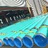
Before coating, the pipe surface is cleaned by shot blasting to a defined surface profile and, where specified, by chemical pretreatment, because coating adhesion depends more on surface preparation than on the coating itself. Three-layer polyethylene or polypropylene is applied by extrusion or side extrusion to the thickness the project specifies, typically in the range of 2.5 mm to 3.7 mm total, and fused epoxy is applied as a thin film, commonly 300 micrometres to 500 micrometres, for higher operating temperature service. Both systems are qualified against recognised standards for pipeline coatings, and the mill records the coating thickness, holiday test result and adhesion test result per length.
Marking is the last chance to preserve traceability. A compliant mark carries the standard designation, the grade, the product specification level, the size, the heat number, the manufacturing process identifier and the mill identifier, applied by stencil or paint in characters that survive transport. Bundling then separates pipe by heat and by coating type so that a mixed load does not force the receiver to re-identify every joint. The document package that should travel with the shipment contains the material test certificate in the 3.1 format, the hydrostatic test record, the nondestructive examination reports, the dimensional inspection record and the coating record. That package is what a third-party inspector will ask for first, and a shipment without it will be held at the port of discharge.
Step 9: What a Purchaser Should Verify Before Release
A disciplined verification sequence takes less than an hour and prevents most of the disputes that arise in line pipe supply. Check that the certificate chemistry sits inside the PSL 2 ceilings for carbon, manganese, phosphorus and sulphur and that the carbon equivalent is reported on the correct basis - CE(IIW) when carbon exceeds 0.12 %, Pcm when it does not. Check that tensile results show yield between 359 MPa and 530 MPa and tensile between 455 MPa and 760 MPa, with elongation above the formula minimum. Check that Charpy testing was done at the ordered temperature with the specified specimen size and that the absorbed energy meets the order. Check the hydrostatic record for holding time and pressure. Check that the nondestructive examination reports name the method and acceptance level, and that the coating record covers every length in the bundle. Finally, confirm that the bevel geometry and the diameter and wall measurements were taken at the pipe end, which is where field welding will actually happen.
Two failures recur often enough to mention. The first is a supplier offering PSL 1 pipe against a PSL 2 order; the strength may be adequate but the carbon equivalent ceiling, the mandatory nondestructive examination and the traceability requirements are all different, and the substitution is visible on the certificate if the specification level field is read carefully. The second is a certificate showing values copied from the heat analysis while the pipe was made from a different heat - a discrepancy a heat number cross-check between mark, certificate and coating record will expose.
FAQ
Q: What are the minimum mechanical properties of API 5L X52 pipe?
X52 requires a specified minimum yield strength of 359 MPa and a specified minimum tensile strength of 455 MPa. Under PSL 2 the yield strength must also fall below 530 MPa and the tensile strength below 760 MPa, so the grade is a window rather than a floor, and the elongation minimum is calculated from the cross-sectional area by the formula in API 5L.
Q: Is X52 pipe seamless or welded?
Both are permitted. API 5L X52 is produced as seamless, high-frequency welded, submerged arc welded with longitudinal seam, and submerged arc welded with helical seam. The grade designation does not fix the process; the order must state it, because the process determines the carbon and manganese maximums that apply and the type of nondestructive examination that can be performed.
Q: Which heat treatment condition should be ordered for X52 line pipe?
As-rolled or normalizing rolling is adequate for most onshore transmission duty at ambient temperature. Normalizing is specified where low-temperature Charpy toughness is required or where the steel chemistry is lean. Thermomechanical controlled processing with accelerated cooling is chosen when a low carbon equivalent is needed to allow field welding without preheat on heavy wall pipe.
Q: What does the carbon equivalent limit mean for the welding procedure?
The 0.43 CE(IIW) ceiling for PSL 2 X52 keeps the heat-affected zone hardenability moderate, which is why most X52 girth welds can be made without preheat at wall thicknesses below about 20 mm in moderate ambient conditions. Above that thickness, or in high-hydrogen environments, the welding procedure still has to be qualified with preheat and with a hydrogen-controlled consumable.
Q: Why is a hydrostatic test required if the pipe already passed ultrasonic testing?
The two tests find different defects. Ultrasonic testing detects planar and volumetric discontinuities in the weld and wall, while the hydrostatic test proves the whole length can carry internal pressure without leakage and without permanent deformation. A pipe can pass ultrasonic testing and still leak at a pinhole in the seam or at a defective end weld.
Q: What documentation should accompany an X52 line pipe shipment?
The minimum set is a material test certificate in the 3.1 format covering heat analysis, product analysis, tensile and impact results, plus the hydrostatic test record, the nondestructive examination reports with method and acceptance level stated, the dimensional inspection record, and the coating inspection record. Each document must reference the heat number marked on the pipe.