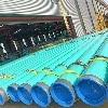
The Design Code Decides the Installation Method
An X52 line pipe with 359 MPa minimum yield strength and a wall thickness selected for the design pressure can be installed in at least four different ways, but the method is not a free choice. It is fixed by the design code, the terrain and the fluid. Onshore gas transmission follows ASME B31.8, liquid pipelines follow ASME B31.4, and offshore submarine lines follow DNV-ST-F101 together with the project pipeline specification. Each code sets its own rules for cover depth, bending limits, weld acceptance, test pressure and coating repair, and a contractor who installs to the wrong one produces documentation that the operator cannot accept even when the physical pipeline is sound.
What the grade contributes is a defined strength level that makes the pipe bendable and weldable in the field. X52 is deliberately moderate: high enough that wall thickness stays economic at transmission pressures, low enough that field cold bending and manual or semi automatic girth welding remain practical without the strict preheat and toughness control that very high strength grades demand. The installation method in turn dictates which mechanical property the buyer should emphasise: buried and cold bent sections reward ductility and a low yield to tensile ratio, offshore sections reward toughness and dimensional consistency, and above ground sections reward coating durability and support design rather than the pipe body itself.
Buried Installation: The Dominant Method
Direct burial covers the overwhelming majority of onshore transmission pipeline length, and the sequence is well defined by the codes. The right of way is cleared and graded, the trench is excavated to line and level, the pipe is strung along the trench on skids, welded, coated at the field joints, inspected, lowered in and the trench is backfilled and compacted. Each step has a numerical acceptance criterion, and the value of a written specification is that these criteria are agreed before the spread mobilises.
| Stage | Controlling parameter | Typical requirement | Governing reference |
|---|---|---|---|
| Trench excavation | Cover to top of pipe | Around 0.9 m minimum in normal class locations, increased at road, rail and water crossings | ASME B31.8 |
| Bedding | Bed and padding material | Fine, stone free material of specified depth below and around the pipe | Project specification |
| Stringing and bending | Field bend radius and strain | Cold bends held to a minimum radius of roughly 40 times diameter, ovality and wrinkle limits applied | ASME B31.8 |
| Girth welding | Weld procedure and acceptance | Qualified procedure, weld acceptance by radiographic or automatic ultrasonic testing | API 1104, ISO 13847 |
| Field joint coating | Cutback and sleeve overlap | Coating continuous with factory coating, holiday free | ISO 21809-3 |
| Lowering in | Lift points and support spacing | Padded slings, controlled multiple side boom lifts, no point loading | Project specification |
| Backfill | Material and compaction | Stone free material adjacent to coating, specified compaction of subsequent layers | ASME B31.8 |
| Testing | Hydrostatic strength and leak test | Strength test at the multiple of maximum allowable operating pressure required by the code, held for the specified duration | ASME B31.8, API RP 1110 |
Two details on buried work cause a disproportionate share of failures. The first is padding. Backfill containing rock, slag or frozen clods damages the coating during compaction, and every damaged area becomes a cathodic protection current sink; where the native soil is rocky, the specification normally requires screened backfill, sand padding or a rock shield layer. The second is the treatment of the bend zone, where the pipe is simultaneously bent, welded and coated, so strain, ovality and coating integrity all have to be checked in one place rather than assumed.
Welding and Joint Integrity in the Field
Girth welds on an X52 transmission line are made to a procedure qualified under API 1104 or EN ISO 13847 and are inspected by radiographic testing, automatic ultrasonic testing, or both. The choice is not arbitrary: automatic ultrasonic testing detects planar defects such as lack of fusion more reliably than radiography on thick walls and is often specified for large diameter, heavy wall pipe, while radiography remains the reference method in many specifications and is required for certain configurations. Acceptance criteria are written as workmanship limits on defect length and density.
Preheat and interpass control are the practical levers the welding engineer uses on X52. Because the grade is weldable with cellulosic electrodes in the vertical down pass on many wall thicknesses, and with low hydrogen processes where hydrogen cracking risk is higher, the procedure must state the minimum preheat, the maximum interpass temperature and the drying and holding requirements for consumables. For wet, cold or high hardness susceptible conditions, a hardness survey on the procedure qualification weld is the cheapest early warning available, and the resulting data are also what a sour service assessment under ISO 15156 will ask for.
Above Ground and Overhead Installation
Above ground installation places the pipe on supports, sleepers or a pipe bridge. Its design problem is not corrosion but structural: the line must accommodate thermal expansion between installation and operating temperature, carry its own weight plus the weight of the contained fluid between supports, and resist wind and seismic loads without over stressing the welds. Expansion is handled by anchors and loops, by sliding or guided supports, and in some designs by cold springing during installation.
The spacing of supports is set by a deflection criterion and by the allowable stress at the support, and both depend on the pipe section properties rather than on the grade alone. Coatings for above ground service must resist ultraviolet exposure and must not embrittle at minimum ambient temperature, which is why a UV stable topcoat is normally specified over the base system. Where an above ground section meets a buried section, the transition zone needs particular care: the pipe must be supported, drained, and electrically isolated or bonded according to the cathodic protection design, otherwise the coating at the soil to air interface is the first place to fail.
Crossings: Casing, Tunnel and Trenchless
Road, rail, river and built up area crossings are where installation method changes most often. A conventional approach is a casing pipe, a larger diameter sleeve through which the carrier pipe is pulled or pushed on spacers, with the annulus sealed at both ends. The casing protects the carrier from external loads, allows the carrier to be replaced, and is often required by the road or rail authority rather than by the pipeline code.
Tunnel and culvert crossings use the same principle at a larger scale: the carrier pipe is installed inside a tunnel or a gallery with supports and spacers, and the design must deal with ventilation, access for inspection, drainage water and, in gas service, the requirement for continuous monitoring. Trenchless methods such as horizontal directional drilling place the pipe in a drilled bore and pull it through, which imposes a tensile load on the pipe body and a abrasion load on the coating; the pull force must be calculated against the pipe tensile capacity and the coating must be specified for the abrasion, since a gouged coating in a bore that cannot be inspected is a permanent liability.
Underwater and Submarine Installation
Submarine pipeline installation is a different discipline because the pipe is laid from a moving vessel under controlled tension rather than buried from the surface. The three common methods are S lay, in which the pipe leaves the vessel over a stinger and forms an S shape to the seabed, J lay, in which the pipe is assembled vertically and leaves almost straight, and reel lay, in which the pipe is spooled on a large drum ashore and unreeled at the field. The choice depends on water depth, pipe diameter, wall thickness and the length of the route.
X52 submarine pipe is normally supplied with a concrete weight coating applied to the corrosion coating, to give the negative buoyancy needed for stability on the seabed, and with sacrificial anodes for cathodic protection. Concrete coating density, thickness and reinforcement are specified against the installation and in place stability analysis, and the coating must survive the tensioner loads and the stinger curvature without cracking. Buckle arrestors are fitted at intervals to limit the length of any propagating buckle, and the route is surveyed for free spans that must be corrected by trenching, rock placement or support installation.
| Method | Typical water depth range | Dominant load on the pipe | Additional requirement |
|---|---|---|---|
| S lay | Shallow to moderate | Bending over stinger plus tension | Stinger geometry matched to allowable strain |
| J lay | Moderate to deep | Vertical tension at the weld station | High capacity tensioner and welding cycle time |
| Reel lay | Shallow to moderate, smaller diameter | Plastic strain during spooling and unreeling | Strain capacity demonstrated by testing |
| Float and sink, bottom pull | Shallow crossings, shore approaches | Buoyancy control and pulling force | Controlled flooding sequence and support during sinking |
Pressure Testing and Commissioning
Every installation method ends in the same place: a pressure test that demonstrates the pipeline has no unacceptable defects and can be operated at the design pressure. On gas transmission lines the strength test is normally conducted at a defined multiple of the maximum allowable operating pressure, held for a specified period, followed by a leak test at a lower pressure. Liquid lines follow the practice of API RP 1110. The test medium is normally water, with quality controlled for chloride content and oxygen to limit corrosion of the internal surface, and the test water must be filtered and its volume measured accurately enough to detect small leaks.
Commissioning adds three steps that are frequently underestimated. Dewatering and drying must reach the dew point required for the product, particularly for gas lines where residual water supports hydrate formation and internal corrosion. Purging must displace air without creating a flammable mixture, which is done with nitrogen or with the product itself under a controlled procedure. And the as built records, including weld maps, coating repair records, test charts and pig run data, must be assembled while the spread is still on site, because reconstructing them afterwards is expensive and often impossible.
Cathodic Protection and Coating Continuity
A buried or submerged X52 line is protected by the combination of a dielectric coating and cathodic protection, following the principles of NACE SP0169 onshore and ISO 15589-1 or ISO 15589-2 offshore. The coating reduces the current demand to an economic level and the cathodic protection covers the holidays, the coating damage and the bare steel at field joints. Impressed current systems with transformer rectifiers and deep or shallow anode groundbeds are common on long lines, while galvanic anodes are used for shorter sections and for offshore pipelines.
Acceptance criteria such as the minus 850 millivolt copper sulphate reference potential for onshore steel, and the corresponding criteria for offshore structures, are measured at test stations after the line is energised and stabilised. The measurement is only meaningful if the coating is electrically continuous and if the pipeline is isolated from other structures at crossings and stations, so isolation joints, casing insulation and test station placement are installation items, not afterthoughts.
Quality Records and Handover
Handover documentation is where an installation is judged. A complete package for an X52 line typically includes material certificates traceable to heat number for every joint, the qualified welding procedures and welder or operator qualifications, non destructive testing reports with defect disposition, field joint coating records including thickness and holiday test results, trench and backfill inspection sheets, bend records with angles and radii, hydrostatic test charts with pressure and temperature, cathodic protection commissioning data, and the as built alignment sheet. Missing or inconsistent records are the most common reason a mechanically sound pipeline is not accepted.
Two record items deserve emphasis because they cannot be recreated. The first is the joint map tying each heat number to a specific location on the line, which is what allows a future integrity assessment to correlate a reported anomaly with a known material source. The second is the coating repair register, which tells the operator where to expect the first cathodic protection current demand and where to look during the first in line inspection.
FAQ
Q: What are the main installation methods for X52 line pipe?
Direct burial, above ground installation on supports or bridges, crossing methods such as casing pipe, tunnel and horizontal directional drilling, and submarine laying by S lay, J lay or reel lay. The applicable design code, terrain and product determine which is used.
Q: How deep must a buried X52 pipeline be?
Cover is set by the design code and the location class. Around 0.9 m to the top of pipe is typical for normal rural locations under ASME B31.8, with greater cover at road, rail and water crossings and where agricultural activity requires it.
Q: Can X52 line pipe be cold bent in the field?
Yes, cold field bending is normal practice on X52 lines. Bends are held to a minimum radius of roughly 40 times the diameter, with limits on ovality and on wrinkle height, and the bend zone is inspected for coating damage before lowering in.
Q: Which welding standard applies to girth welds?
API 1104 or EN ISO 13847 for onshore pipeline girth welds, with acceptance by radiographic testing, automatic ultrasonic testing or both. Offshore projects normally add the weld acceptance requirements of the pipeline design specification.
Q: Why does submarine X52 pipe need concrete coating?
Concrete weight coating provides the negative buoyancy required for seabed stability and protects the corrosion coating during laying. Its density and thickness come from the stability analysis, and it must survive tensioner loads and bending over the stinger.
Q: What test pressure is used before commissioning?
The strength test is conducted at the multiple of maximum allowable operating pressure required by the applicable code, held for the specified duration, and is followed by a leak test. Water is the normal test medium, with chloride and oxygen content controlled.
Q: Does the installation method change the pipe specification?
Yes. Trenchless and submarine methods impose pulling and bending loads that must be checked against the pipe tensile and strain capacity, and above ground sections need coating systems resistant to ultraviolet exposure. The same X52 grade can require different wall thickness, toughness and coating depending on how it is installed.