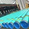
What Pressure Resistance Really Means for an X52 Oil Pipe
Pressure resistance is the internal pressure at which a tube stops behaving elastically and begins to yield, bulge or leak. For an X52 grade oil pipe the number is never a single catalogue figure, because it is produced by three inputs acting together: the specified minimum yield strength of the steel, the actual wall thickness left after tolerance and corrosion allowance, and the outside diameter that the hoop stress has to act on. Change any one of them and the answer moves. This is why a calculation, not a data sheet claim, is the correct starting point for sizing an X52 string.
The grade itself belongs to the API SPEC 5L family, where X52 is defined by a specified minimum yield strength of 359 MPa and a specified minimum tensile strength of 455 MPa. In ISO 3183 the identical steel carries the designation L360. X52 is a line pipe grade, not a casing grade: API SPEC 5CT casing and tubing is built around J55, K55, N80, L80, C90, T95, P110 and Q125, so a project that needs a 359 MPa yield steel for oil service normally specifies API 5L X52 / ISO 3183 L360 line pipe and designs the connection and pressure envelope accordingly. Mixing the two standards loosely is one of the most common documentation errors seen in procurement files.
Grade Position of X52 in the Strength Ladder
Pressure capacity scales almost linearly with yield strength at constant geometry, so grade selection is the first lever. Grade B offers 241 MPa minimum yield, X42 offers 290 MPa, X46 offers 317 MPa, X52 offers 359 MPa, X60 offers 414 MPa, X65 offers 448 MPa and X70 offers 483 MPa. Moving from Grade B to X52 at the same wall and diameter therefore raises the calculated yield pressure by roughly half, which is often enough to avoid a heavier and more expensive wall.
Product specification level matters as much as grade. PSL 1 pipe is verified by tensile and hydrostatic testing only, while PSL 2 adds maximum limits on yield and tensile strength, a maximum yield-to-tensile ratio, mandatory Charpy impact testing and tighter chemistry control. In API 5L PSL 2 the X52 requirement is a yield strength window of 359 MPa to 530 MPa and a tensile strength window of 455 MPa to 760 MPa, with a maximum yield-to-tensile ratio of 0.93 for the base grade and 0.93 for the R, N, Q and M suffixes when the higher ratios apply. For pressure design this means PSL 2 gives a bounded, predictable strength that a design engineer can use with confidence, while PSL 1 only guarantees a floor.
Barlow's Formula and the Design Factor
The thin-wall relationship used across pipeline codes is P = 2 S t / D, where P is the internal pressure, S is the allowable hoop stress, t is the nominal wall thickness and D is the specified outside diameter. The formula is valid where the diameter-to-thickness ratio is above roughly 20; below that the thick-wall Lamé solution gives a more conservative and more accurate answer, and for very heavy walls the difference between the two approaches becomes commercially significant.
The allowable stress S is not the yield strength. It is the specified minimum yield strength multiplied by a design factor written into the applicable code. ASME B31.8 uses factors of 0.72, 0.60, 0.50 and 0.40 across its location classes, so the same X52 pipe in a rural Class 1 location can be rated at 72 percent of yield while a Class 4 crossing or station area is held to 40 percent. ASME B31.4 applies a comparable set of factors for liquid lines, and ASME B31.3 uses allowable stress values tabulated in its own stress tables for process piping. The design factor is therefore a legal and safety decision, not a mill option, and it must be stated in the purchase specification.
Worked Pressure Comparison for X52 Sizes
The table below applies P = 2 S t / D with S equal to 359 MPa times a design factor of 0.72, and expresses the result in both bar and psi so that the magnitude of each variable can be compared quickly. The values are calculated at nominal wall without corrosion allowance, which is deliberate: they show the ceiling, not the working pressure.
| Outside diameter (mm) | Nominal wall (mm) | D/t ratio | Calculated yield pressure, F = 0.72 (bar) | Calculated yield pressure (psi) |
|---|---|---|---|---|
| 114.3 | 6.02 | 19.0 | 272 | 3,945 |
| 168.3 | 7.11 | 23.7 | 218 | 3,162 |
| 219.1 | 8.18 | 26.8 | 193 | 2,799 |
| 273.1 | 9.27 | 29.5 | 175 | 2,538 |
| 323.9 | 10.31 | 31.4 | 165 | 2,393 |
| 406.4 | 12.70 | 32.0 | 161 | 2,335 |
Two conclusions follow directly. First, doubling the wall roughly doubles the pressure, which makes wall thickness the most efficient lever once the grade is fixed. Second, diameter works against pressure: growing from 114.3 mm to 406.4 mm at a similar D/t ratio cuts the rating by about 40 percent, because hoop stress is spread over a larger circumference.
Wall Thickness Tolerance and the Effective Pressure Boundary
The calculation above uses nominal wall, but the pipe that arrives on site is thinner somewhere around its circumference. API 5L permits a defined negative wall thickness deviation, and PSL 2 tolerances are tighter than PSL 1 for the same size range. A disciplined design subtracts the full permitted negative deviation before computing pressure, then subtracts the corrosion allowance, then subtracts any allowance for threading, grooving or grinding of the weld seam. In a sour or wet service the corrosion allowance can easily be 3 mm, which on a 8.18 mm wall removes more than a third of the pressure capacity.
For a threaded and coupled oil string there is a second reduction. Threading cuts metal from the pipe body wall, so the pressure resistance of the connection and of the threaded section, not of the plain body, usually governs the string design. API SPEC 5B defines the thread form and gauging, and the coupling design determines the joint efficiency. A joint efficiency below 100 percent means the string is only as strong as its weakest threaded section.
Weight per Metre as a Cross-Check on Geometry
Buyers cross-check the wall thickness they think they ordered against the mass they were actually shipped by using the theoretical mass formula M = 0.02466 x (D - t) x t, which returns kilograms per metre for carbon steel at a density of 7.85 g/cm3. The constant 0.02466 is derived from pi/1000 times the density, so the formula is geometry, not opinion. For an austenitic stainless tube the density rises to roughly 7.9 to 8.0 g/cm3 and the constant becomes about 0.02491; duplex and super-duplex grades sit in the same band.
The weight check is more useful than it looks. A consignment that weighs 4 percent light is usually a wall thickness deviation, and a wall 4 percent thin is a 4 percent pressure loss plus a change in the D/t ratio that may push the design outside the validity range of the thin-wall formula. Weight, wall thickness measured by ultrasonic gauge, and the mill certificate value should all agree within the permitted tolerance before the pipe is accepted into a pressure service.
Hydrostatic Testing and What the Certificate Proves
API 5L requires each length to be hydrostatically tested, with the test pressure for PSL 2 normally computed to produce a hoop stress equal to the specified minimum yield strength for the grade, and held for a defined minimum period before inspection for leakage. The test pressure therefore validates the pipe body against its own wall and diameter; it does not validate a design pressure chosen by the buyer's engineer, and it does not simulate the design factor. A pipe that passes the mill test at 100 percent of yield hoop stress can still be unsuitable for a system designed at 0.72 because the design pressure depends on the corrosion allowance and the connection efficiency that the mill knows nothing about.
Acceptance should be built on the inspection documents rather than the test itself: an EN 10204 type 3.1 certificate tied to the heat number, the chemical composition against the PSL 2 table, the tensile results against the yield and tensile windows, the Charpy absorbed energy at the specified test temperature, the non-destructive examination method and coverage, and the dimensional record. For welded X52 the weld seam is additionally examined by ultrasonic or radiographic methods under ISO 10893 or the API 5L annexes, and the seam is the location where pressure-driven failure most often originates.
Derating for Temperature, Corrosion and Sour Service
The Barlow result is a room-temperature number for sound metal. Three derating rules usually apply on top of it. Temperature: yield strength falls as metal temperature rises, and the applicable code supplies a temperature derating factor that must be applied above roughly 120 degrees Celsius for carbon steel line pipe. Metal loss: internal corrosion, erosion or mechanical damage reduces t, and pressure capacity falls in direct proportion, which is why corrosion allowance and intelligent pigging intervals are part of the pressure design file, not a maintenance afterthought.
Sour service adds a materials qualification requirement rather than a simple factor. ISO 15156 and NACE MR0175 govern the acceptable hardness, chemistry and heat treatment for wet H2S exposure, and X52 in the as-rolled or normalised condition may require restriction of hardness and of the weld procedure. A pressure calculation that ignores the sour service metallurgical limits can produce a pipe that is strong enough and still not permitted for the environment.
Common Assumptions That Overstate Pressure Resistance
The first is using the mill certificate tensile strength instead of the specified minimum yield strength. The certificate value is a measured point for one heat, and design must use the standardised minimum. The second is ignoring the diameter used by the code, which is the specified outside diameter rather than a measured average. The third is applying a design factor of 0.72 in a location class that requires 0.5 or 0.4. The fourth is treating the hydrostatic test pressure as the allowable working pressure, which overstates capacity by the inverse of the design factor, roughly 39 percent at 0.72.
A fifth assumption is more subtle: engineers sometimes check the pipe body but not the fitting, flange or valve rating. ASME B16.5 and ASME B16.47 flanges have their own pressure-temperature ratings that fall off with temperature, and a Class 300 flange at elevated temperature may rate lower than the attached X52 pipe. The system pressure resistance is always the lowest component in the chain, and procurement should require a rating statement for every component in the pressure boundary.
FAQ
Q: What is the pressure resistance of X52 oil pipe?
There is no single value. It is calculated from P = 2 S t / D with S equal to the 359 MPa specified minimum yield strength of X52 multiplied by the code design factor, typically 0.72 for onshore pipelines, so the result depends entirely on diameter and wall thickness.
Q: Is X52 an API 5CT casing grade?
No. API SPEC 5CT covers grades such as J55, K55, N80, L80, C90, T95, P110 and Q125. X52 is an API SPEC 5L line pipe grade, designated L360 in ISO 3183, and is used for oil and gas lines rather than as a casing grade.
Q: What are the yield and tensile strength limits of X52?
API 5L specifies a minimum yield strength of 359 MPa and a minimum tensile strength of 455 MPa. In PSL 2 the yield is bounded at 359 to 530 MPa and the tensile at 455 to 760 MPa, with a maximum yield-to-tensile ratio of 0.93.
Q: How much pressure does wall thickness tolerance cost?
Pressure capacity is proportional to wall thickness, so the full permitted negative wall deviation must be deducted before calculation. If the negative deviation is 10 percent of nominal wall, the usable pressure capacity is also about 10 percent lower than the nominal-wall calculation suggests.
Q: Does a passing hydrostatic test approve my design pressure?
No. The mill test verifies the pipe body at a hoop stress tied to the grade's minimum yield strength. The design pressure is governed by the code design factor, the corrosion allowance and the connection efficiency, none of which the mill test evaluates.
Q: Why is the thick-wall formula sometimes required?
Barlow's formula assumes a thin wall in which hoop stress is uniform through the thickness. Below a diameter-to-thickness ratio of about 20 the assumption breaks down and the Lamé thick-wall solution should be used, giving a lower and more realistic pressure capacity.