Why One Pipe Specification Cannot Serve Gas, Oil and Water
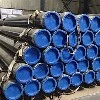
Gas, crude oil, refined products and water are all moved through carbon steel line pipe, and in outline the hardware looks the same: a long cylindrical pressure vessel joined end to end. The service conditions, however, pull the specification in different directions. Natural gas is compressible and low in density, so transmission economics push toward large diameter and high pressure; the consequence is a design that is dominated by fracture control and by resistance to running shear fracture. Crude oil and products are essentially incompressible, so a given throughput needs a much smaller diameter, and the governing risks shift toward internal corrosion, wax and hydrate behaviour, and batch contamination. Water is the least demanding fluid mechanically, but the most demanding in terms of internal lining, because tuberculation and cement-mortar protection decide the service life of the main.
All three services converge on the same technical foundation: API 5L line pipe, with its identical international adoption ISO 3183 and its domestic counterpart GB/T 9711. What changes between services is the product specification level, the grade, the toughness requirement, the weld seam inspection extent, the coating system and the design code used to convert pressure into wall thickness.
Product Specification Level: The First Real Decision
API 5L defines two specification levels. PSL1 sets chemical limits on carbon, manganese, phosphorus and sulphur only, and requires tensile and yield testing plus a hydrostatic test; it is a workmanlike specification for general service. PSL2 fixes the chemistry much more tightly, adds silicon and carbon equivalent limits, requires Charpy V-notch testing, and requires non-destructive inspection of the weld seam over the full length.
The practical distinction for a buyer is this: PSL1 pipe is acceptable where the design code permits a lower safety regime and where the fluid is not hazardous, for example low-pressure water mains, piling, and general structural or utility service. PSL2 is the normal choice for gas transmission, for high-pressure liquid lines, for low-temperature installation and for any line where a fracture-mechanics based assessment is required. Specifying PSL2 without also specifying impact test temperature and absorbed energy defeats the purpose, because the level alone does not fix toughness.
Grades and Strength Levels
Grade designations follow a simple rule in API 5L: the letter X is followed by the specified minimum yield strength in thousands of pounds per square inch. X42 is therefore 42 000 psi minimum yield, or 290 MPa. Grades below X42 use letters - Grade A25, Grade A, Grade B - and above X70 the range extends to X80 in commercial line pipe service.
| Grade | Min yield, PSL1 | Min tensile, PSL1 | PSL2 yield range | PSL2 tensile range |
|---|---|---|---|---|
| Grade B | 245 MPa | 415 MPa | 245 to 450 MPa | 415 to 760 MPa |
| X42 | 290 MPa | 414 MPa | 290 to 496 MPa | 414 to 760 MPa |
| X46 | 320 MPa | 434 MPa | 320 to 435 MPa | 434 to 760 MPa |
| X52 | 360 MPa | 460 MPa | 360 to 530 MPa | 460 to 760 MPa |
| X60 | 415 MPa | 520 MPa | 415 to 565 MPa | 520 to 760 MPa |
| X65 | 450 MPa | 535 MPa | 450 to 600 MPa | 535 to 760 MPa |
| X70 | 485 MPa | 570 MPa | 485 to 635 MPa | 570 to 760 MPa |
| X80 | 555 MPa | 625 MPa | 555 to 705 MPa | 625 to 825 MPa |
PSL2 grades also carry a defined maximum, which matters more than buyers expect. A steel that exceeds the upper yield limit is rejected even though it is stronger, because excessive yield-to-tensile ratio reduces the plastic deformation capacity that a pipeline needs to arrest a propagating fracture. That is why X70 ordered as "minimum 485 MPa" without the upper bound is not equivalent to X70 to API 5L.
Pipe Types and Where Each Fits
Line pipe is supplied seamless or welded, and the welded family splits into three commercially distinct products. The choice is driven by diameter, wall thickness, toughness requirement and price per metre.
| Type | Typical outside diameter | Typical wall | Best fit |
|---|---|---|---|
| Seamless, hot rolled or cold drawn | 21.3 mm to 660 mm | 2.8 mm to 60 mm and heavier | High pressure small and medium diameter, sour service, thick wall, high collapse resistance |
| ERW / high-frequency welded | 21.3 mm to 610 mm | 1.5 mm to 20 mm | Medium diameter transmission and distribution, structural and utility lines |
| LSAW, longitudinal submerged arc | 406 mm to 1420 mm | 6 mm to 40 mm | Large diameter high pressure gas and oil trunk lines |
| SSAW, helical submerged arc | 219 mm to 3000 mm | 5 mm to 25 mm | Very large diameter water and low pressure lines, piling, large gas mains |
Seamless pipe has no weld seam to inspect but pays for that with higher dimensional scatter and a lower size ceiling. ERW is the most economical per tonne in its range and, with seam normalising and full-length seam inspection, is accepted for gas service under API 5L PSL2. LSAW gives the best combination of large diameter, heavy wall and weld toughness, which is why it dominates cross-country gas transmission. SSAW produces the largest diameters economically but has a helical seam that is longer per metre of pipe, so it is normally preferred where pressure is moderate and diameter is extreme.
Converting Pressure into Wall Thickness
Pipeline design codes do the arithmetic: ASME B31.8 for gas transmission and distribution, ASME B31.4 for liquid pipelines, and ISO 13623 internationally. The governing equation is a thin-wall hoop stress expression in which the allowable stress is the specified minimum yield strength multiplied by three factors: a design factor F, a longitudinal joint factor E, and a temperature derating factor T.
The design factor is where the codes diverge sharply. Under ASME B31.8 the factor falls as population density rises - commonly 0.72 in a Class 1 location, 0.60 in Class 2, 0.50 in Class 3 and 0.40 in Class 4 - so the same pressure in a populated area needs materially thicker wall or a higher grade. The joint factor E is 1.00 for seamless and for welded pipe that has passed the required quality checks, which is precisely why the weld inspection regime is worth paying for: it buys back wall thickness. Practically, a line specified as X65 with 0.72 design factor can be built with thinner wall than the same line in X52, and the grade upgrade usually wins on total installed cost once transport and welding savings are counted.
Line Pipe Ends and Field Jointing
Pipe ends are supplied plain (bevelled), threaded, or with special geometry. Transmission lines are almost always bevelled for girth welding; the bevel angle and land are specified so that the root gap and the welding procedure produce full penetration on the first pass. Smaller distribution and utility lines may use threaded and coupled ends to API 5B, and some water and slurry lines use mechanical or push-on joints.
For girth welding, the pipe end dimensional control is as important as the steel: out-of-roundness, end squareness and wall thickness mismatch at the joint all translate into fit-up stress. A specification that holds end tolerances tightly is cheaper in the field than a specification that holds only chemistry and tensile properties, because field repair rates dominate construction cost.
Internal and External Protection
External coating for buried lines is usually a three-layer polyethylene or polypropylene system to ISO 21809-1, fusion bonded epoxy to ISO 21809-2, or, in domestic practice, three-layer PE to GB/T 23257. Each system has a defined operating temperature ceiling and a defined resistance to mechanical damage during backfill; specifying the wrong one shows up as coating disbondment within a few years. Concrete weight coating to ISO 21809-5 is added on offshore and swamp crossings for negative buoyancy, and it also provides mechanical protection.
Internal protection depends entirely on the fluid. Dry gas needs nothing beyond cleanliness. Wet gas and multiphase service need corrosion-resistant alloy cladding or a strict chemical inhibition and monitoring regime, and the carbon steel itself must comply with ISO 15156 / NACE MR0175 if hydrogen sulphide is present - the practical consequence being a hardness cap of 22 HRC and mandatory hardness verification on the weld and heat-affected zone. Water mains are normally lined with cement mortar to AWWA C205 or ISO 4179, or with epoxy for potable water where the lining must also meet drinking-water contact approvals.
Testing and Acceptance at the Mill
Every line pipe order should close on a defined test regime, because the tests are what convert a material certificate into an engineering assurance. The baseline is the hydrostatic test, whose pressure is calculated from hoop stress rather than chosen arbitrarily, held for a minimum period and recorded. PSL2 pipe adds non-destructive inspection of the entire weld seam, generally by automated ultrasonic testing to ISO 10893-11, with radiography to ISO 10893-6 where the geometry makes UT unreliable.
Toughness testing is the other non-negotiable. Charpy V-notch specimens are taken transverse to the pipe axis from the body, the weld and the heat-affected zone, at a temperature set by the design minimum. Drop-weight tear testing is specified for gas transmission lines where resistance to running shear fracture must be demonstrated, and the resulting shear-area percentage is a contractual acceptance criterion, not a formality. Chemistry, carbon equivalent, hardness and dimensional checks complete the routine package, and a third-party inspection release is normal on transmission projects.
Selecting the Right Specification: A Practical Sequence
Start from the fluid and the design pressure, not from a grade. Fix the design code first, because it dictates the design factor and therefore the wall thickness. Then compute the wall thickness for two or three candidate grades and compare total installed cost, including welding, transport and coating. Then set the product specification level from the consequence of failure and the design temperature. Only after those three steps should the purchase order be drafted, and it should state: specification, level, grade with delivery condition, outside diameter, wall thickness, length range, end finish, coating system, impact test temperature and energy, NDT extent, and documentation package.
The most common procurement error is specifying a high grade to save wall thickness while leaving toughness and weld inspection at PSL1 level. That produces a line with high strength and poor fracture resistance, which is the least desirable combination available. Strength, toughness and inspectability have to move together.
FAQ
Q: Can the same pipe be used for natural gas and for water?
Physically yes, but the acceptance criteria and the lining differ. Gas service requires PSL2 with defined toughness and full seam inspection because of fracture risk, while water service usually tolerates PSL1 with a cement-mortar or epoxy lining. Using a gas-grade pipe for water is technically safe but commercially wasteful; using a water-grade pipe for gas is a design-code violation.
Q: What diameter is used for a main oil pipeline?
Trunk lines handling large crude volumes commonly run from about 400 mm to 1200 mm outside diameter, with the exact size set by throughput, pump pressure and terrain. Gathering and feeder lines to the trunk typically use 150 mm to 400 mm pipe. The decision is an economic optimisation of pumping power against capital cost, not a fixed standard.
Q: Does a higher grade always mean a better pipeline?
No. Higher grade allows thinner wall for the same pressure, which reduces steel mass and freight, but it raises the yield-to-tensile ratio and narrows the acceptable chemistry window, making welding procedure qualification stricter and heat-affected zone toughness harder to guarantee. Many medium-pressure lines are optimised at X52 or X60 rather than at the highest available grade.
Q: How is the hydrostatic test pressure set?
The test pressure is derived from the hoop stress formula using the specified wall thickness and a permitted fraction of the yield strength, capped so that the pipe is not overstressed. The hold time and the pressure recording requirements come from the ordering standard, and the test is witnessed or recorded for the mill test certificate.
Q: What does the R, N, Q or M suffix after a grade mean?
The suffix defines the delivery condition. As-rolled is designated R, normalised is N, quenched and tempered is Q, and thermomechanically rolled is M. The condition changes the microstructure, the toughness and the welding behaviour, so a grade without a stated suffix is an incomplete specification for PSL2 pipe in low-temperature or sour service.
Q: How should line pipe be stored before installation?
Stack on timber or sand berms with the coating protected from rock contact, keep the stack height within the limit that avoids ovalisation of the bottom courses, and shade fusion bonded epoxy coated pipe from prolonged direct sun if the product data requires it. End protectors stay on until the pipe reaches the trench, because a damaged bevel is a field rework item.